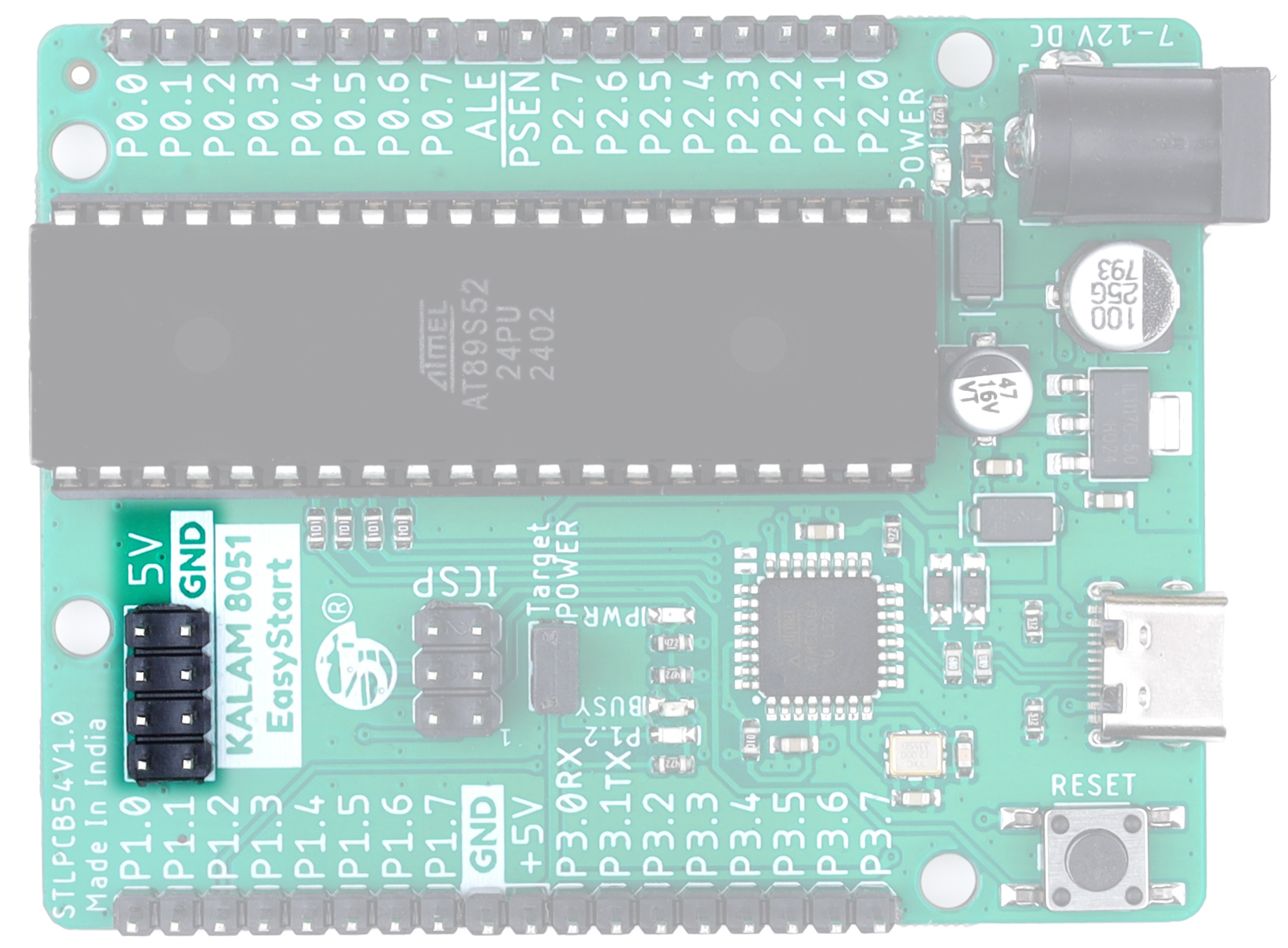
Kalam 8051 EasyStart - Hardware Details
Power Supply Section
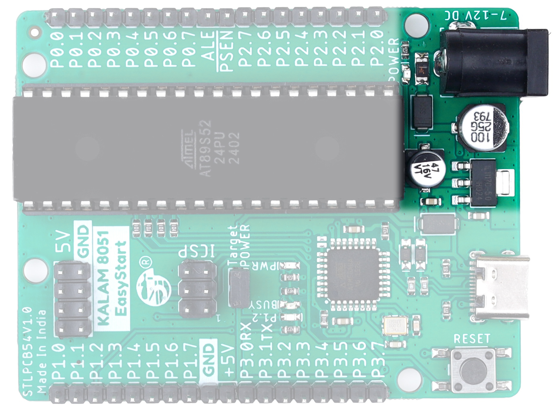
The power supply section accepts 7–12V DC input and converts it to stable 5V output using an onboard LM1117-5V regulator. It also includes a PPTC fuse, reverse polarity protection, and a red power indication LED to ensure smooth and safe power delivery to the MCU.
USBasp Programmer
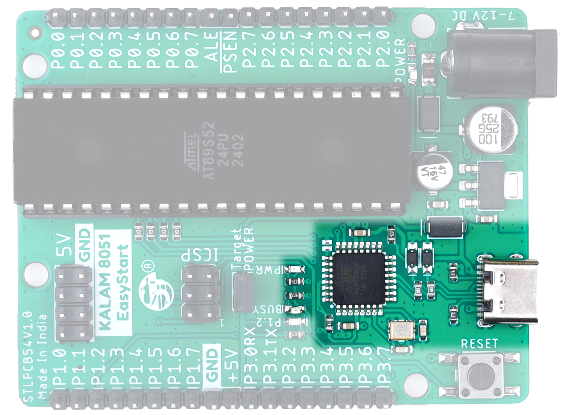
The onboard USB programmer enables direct programming of the AT89S52 MCU through USB without requiring external programming hardware, making firmware uploading simple and convenient.
The ATmega8A on the programmer section is dedicated exclusively to the onboard USB programming function. It is pre-programmed and cannot be used as a general-purpose microcontroller in user applications.
ICSP Connection
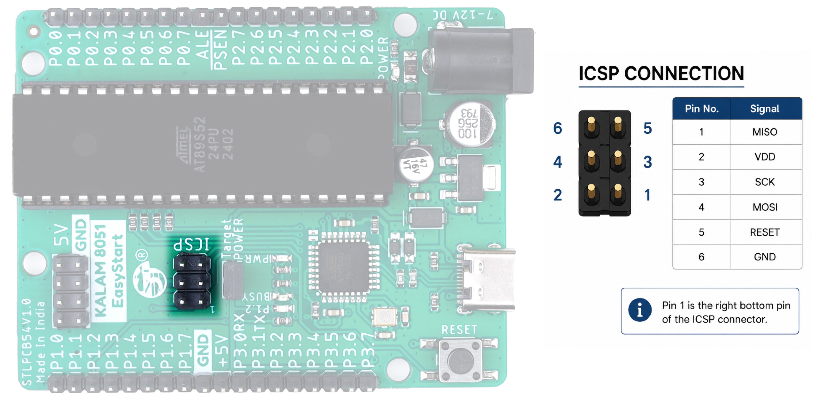
The onboard ICSP connection allows programming of external AT89S52/8051 MCUs using the board’s built-in USB programmer. It provides a simple and convenient way to upload firmware to external target MCUs during development and testing.
MCU - AT89S52
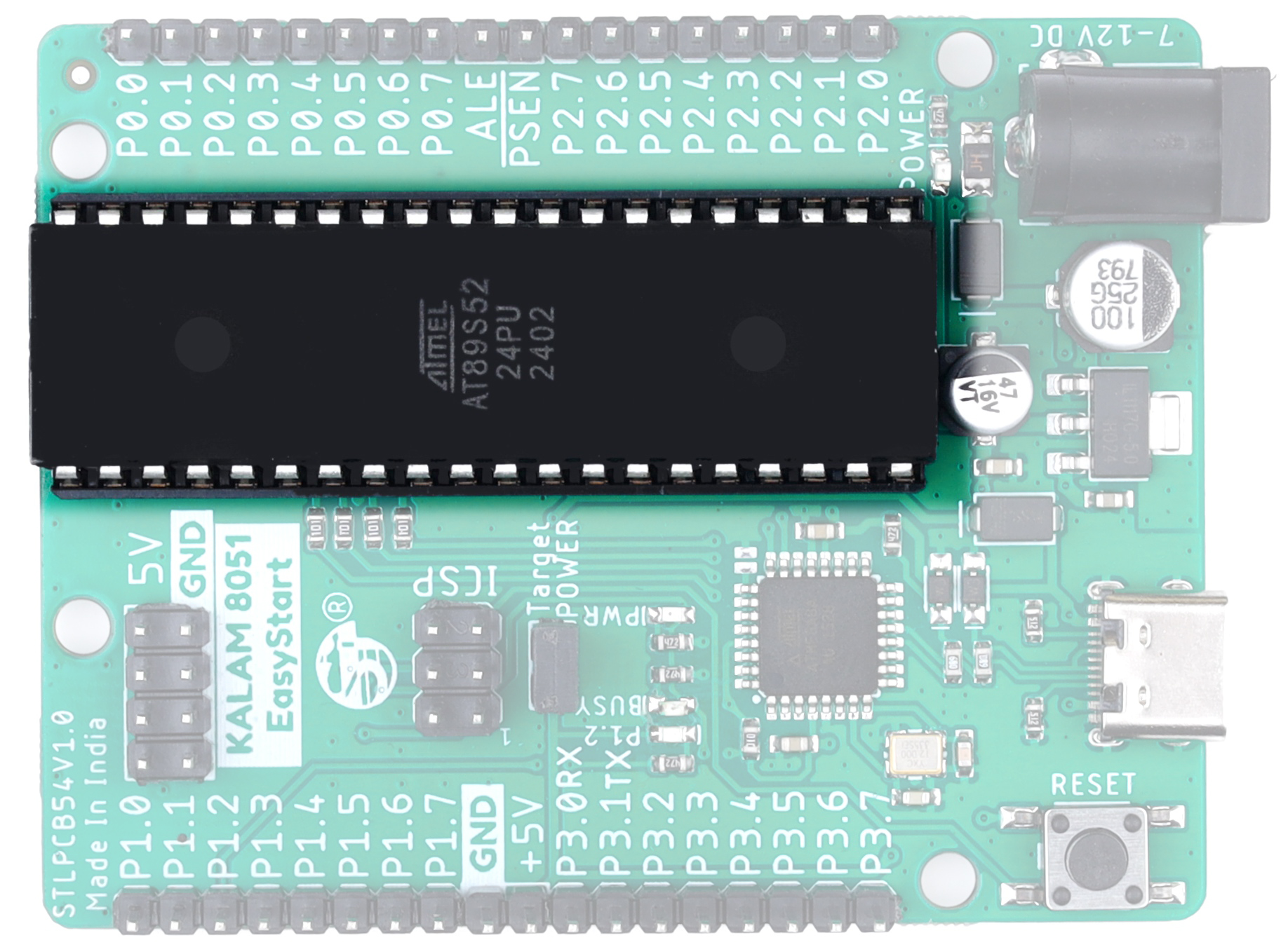
The board is powered by the AT89S52 8051 microcontroller, providing reliable performance for embedded system development, educational projects, and industrial control applications.
Breakout Pins
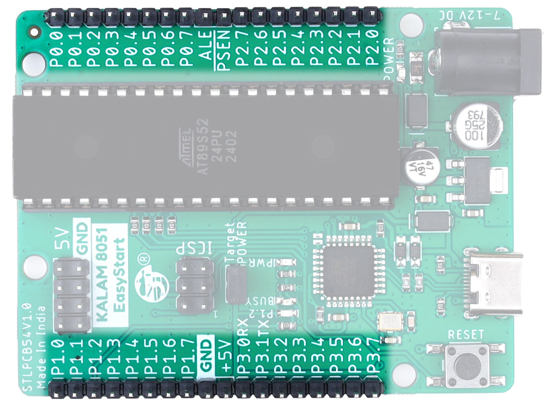
All important MCU GPIO pins are available on standard header breakout pins for easy interfacing with external modules, sensors, displays, and development peripherals. The board layout is designed for quick prototyping and simplified hardware connections.
Reset Switch
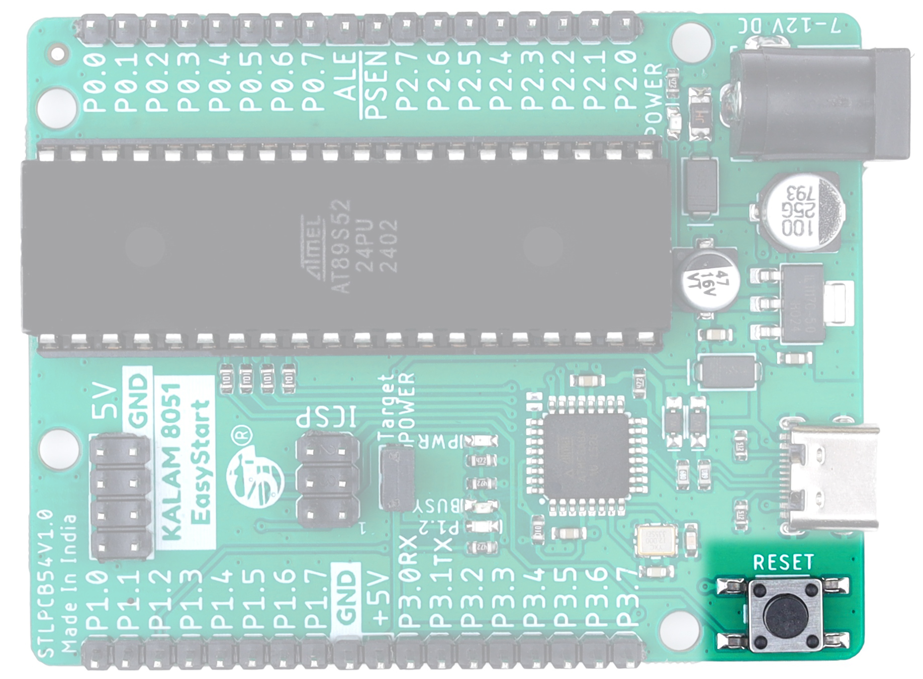
The onboard reset switch allows manual restarting of the MCU during development and testing. It is useful for firmware debugging and quick system reset operations.
LED P1.2 Indicator
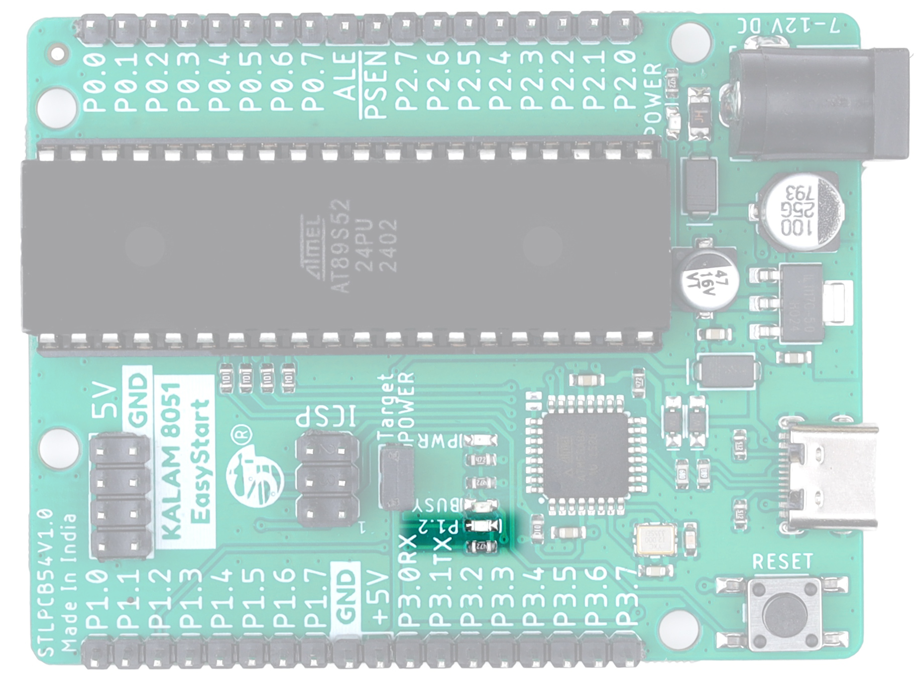
An onboard Blue LED is connected to MCU pin P1.2 for testing, debugging, and basic output indication. It is useful for learning GPIO control, blinking applications, and firmware debugging.
USB Power for Onboard MCU
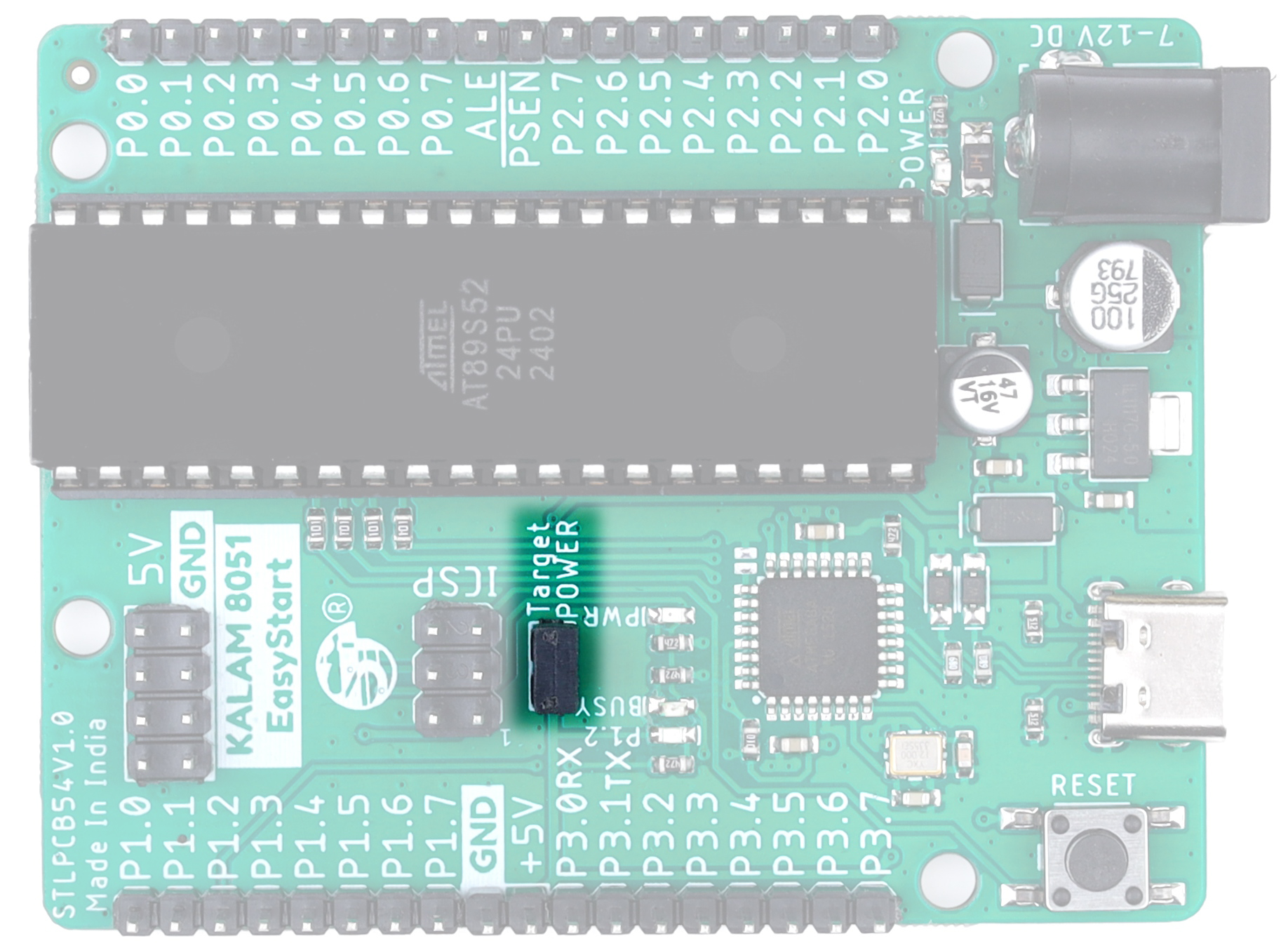
The onboard USB programmer section can directly provide regulated power to the MCU and development board, enabling convenient programming through USB connection.
Jumper Closed
When the jumper is closed (installed), the onboard USB programmer supplies regulated power to the target MCU and development board through the USB connection.
Jumper Open
When the jumper is open (removed), USB power is disconnected from the target circuit. In this mode, the target MCU and peripherals must be powered from an external power source.
Ensure only one power source is used at a time to avoid power conflicts.
External Power Output
The board provides regulated 5V power output for external modules, sensors, and peripheral devices when the board is powered through the USB connection. The onboard power supply section ensures stable and reliable power delivery for connected external circuits.
When powered through USB, the maximum available output current is 500mA. Ensure that the total current consumption of all connected devices does not exceed this limit.